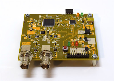
Recently, I posted a teardown of a CTS 10MHz Oven Controlled Crystal Oscillator (OCXO). Using the unit that I opened up, I was able to work out the schematic for the boards inside.
![]()
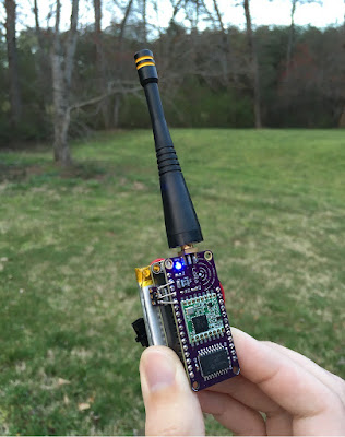
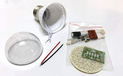
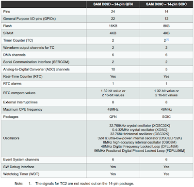
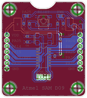
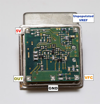
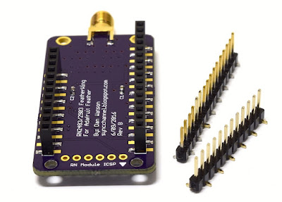
Internally, the OCXO consists of two boards. One is the larger, main board with most of the components. It contains the oscillator circuit, voltage control and voltage reference circuitry, heater control, and output buffering/filtering. The ceramic board adhered to the bottom of it is the heater. It contains two power devices and two temperature monitoring devices. The 10MHz crystal is bonded to that ceramic board, but connects directly to the main board. The two boards connect via five pins that are directly soldered.
The board assembly is mounted on pins inside the can, which also extend to the outside of the unit. The only insulation material in the unit is the small, brown strip seen in the above photo. It wraps around one side of the crystal when everything is assembled.
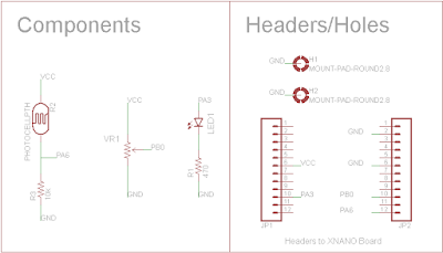
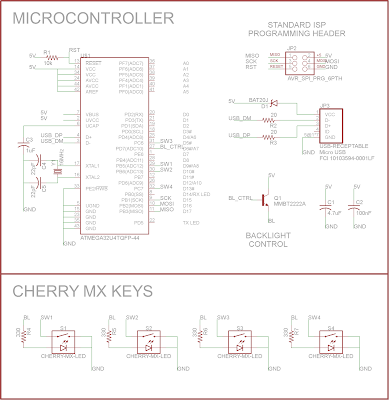
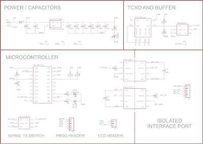
Externally, the OCXO has five pins: 5V, GND, 10MHz OUTPUT, VREF, and EFC. Those pin names are used as labels for various nodes in the schematic below where they connect.
I was able follow the components and traces on the boards to work out the schematic. After getting a rough outline, I removed all of the capacitors and inductors and measured their values out of circuit as accurately as I could.
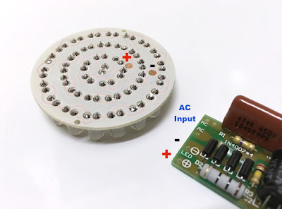
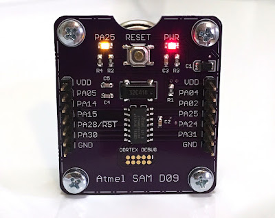
There are only two ICs on the main board. One is an LM2902 quad opamp. Three of the opamps are used and one is terminated. The other IC is a TC7S00FU single NAND gate that is used as an output buffer.
The two power devices on the heater board are BST50 NPN darlington transistors. The temperature sensors are TI LM45s.
![]()

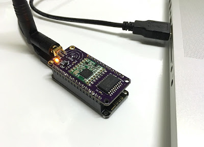
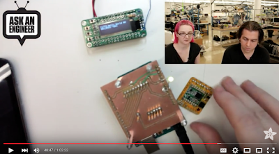
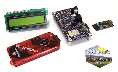
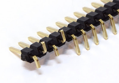
This is what's left of the CTS OCXO I did the teardown on. Poor thing...
Construction
Internally, the OCXO consists of two boards. One is the larger, main board with most of the components. It contains the oscillator circuit, voltage control and voltage reference circuitry, heater control, and output buffering/filtering. The ceramic board adhered to the bottom of it is the heater. It contains two power devices and two temperature monitoring devices. The 10MHz crystal is bonded to that ceramic board, but connects directly to the main board. The two boards connect via five pins that are directly soldered.
The board assembly is mounted on pins inside the can, which also extend to the outside of the unit. The only insulation material in the unit is the small, brown strip seen in the above photo. It wraps around one side of the crystal when everything is assembled.
Externally, the OCXO has five pins: 5V, GND, 10MHz OUTPUT, VREF, and EFC. Those pin names are used as labels for various nodes in the schematic below where they connect.
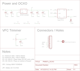
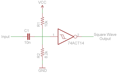
Schematic
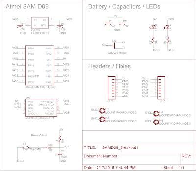
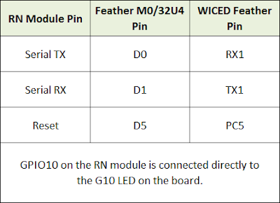
I was able follow the components and traces on the boards to work out the schematic. After getting a rough outline, I removed all of the capacitors and inductors and measured their values out of circuit as accurately as I could.
There are only two ICs on the main board. One is an LM2902 quad opamp. Three of the opamps are used and one is terminated. The other IC is a TC7S00FU single NAND gate that is used as an output buffer.
The two power devices on the heater board are BST50 NPN darlington transistors. The temperature sensors are TI LM45s.

Schematic of the CTS 1960017 10MHz OCXO.
Click to make it larger, then right click to download it.
Wrap Up
So what do you think? Is the circuit simpler than you expected, or more complex? It's very interesting to see this take on a modern 5V, 10MHz OCXO. I suspect internal construction and complexity varies greatly between device families. Please post any questions, comments, or corrections below.
Thanks for reading!
- Dan W.